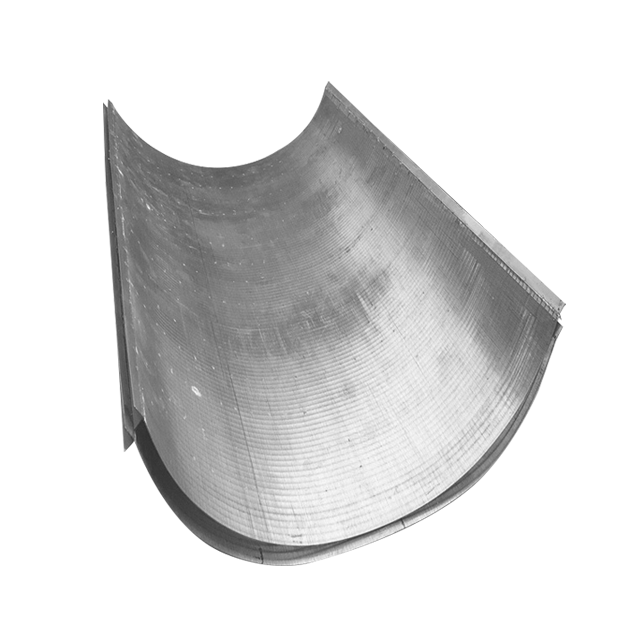
High-volume solid-liquid separation creates major operational bottlenecks in continuous industrial processes. Facilities face mounting costs associated with mechanical separation downtime and the constant maintenance of moving parts. Poorly specified static screens compound the problem by causing blinding, overflow, or suboptimal dehydration, directly impacting throughput. The Industrial Sieve Bend Screen (DSM screen) solves these challenges as a high-capacity, gravity-fed solid liquid separation screen. It minimizes operational expenditure while delivering precise particle classification, medium removal, and dewatering. By leveraging fluid dynamics rather than mechanical force, this equipment provides a reliable, continuous separation method. Readers will learn the underlying mechanics, design specifications, application fits, and sizing criteria needed to optimize plant efficiency.
Mechanism: Sieve bend screens utilize gravity, tangential flow, and the Coanda effect across curved wedge wire to achieve efficient solid-liquid separation without moving parts.
Design Efficiency: The perpendicular orientation of wedge wire profiles relative to the feed flow slices the fluid, allowing liquids to pass while retaining solids at half the size of the actual slot opening. The curved design inherently offers significantly greater capacity than flat static screens.
Application Fit: Optimal for high-moisture slurries in wastewater treatment, mineral processing, and food production where continuous, low-maintenance dewatering is required.
Vendor Selection: Choosing the right sieve bend screen manufacturer requires evaluating custom slot tolerances, material certifications (e.g., 304/316L stainless steel), frame mounting integrity, and application-specific hydraulic loading calculations.
The Working Principle of an Industrial Sieve Bend Screen
Engineers must understand the fluid dynamics of static screens to accurately predict separation efficiency and prevent system bypass. A proper grasp of gravity-driven separation mechanics ensures optimal performance across varying flow conditions. Slurry enters the unit via a feed box or hopper. This component converts hydrostatic pressure into a uniform, tangential flow. The fluid then directs vertically over the full width of the upper screen surface. The Coanda effect plays a critical role here. Fluid clings to the concave curved profile wire, drawing liquid and undersized particles through the slots. Larger solids cascade down the screen face for collection or further processing.
Gravity-Driven Solid-Liquid Separation Mechanics
The feed mechanism dictates the initial success of the separation. If the slurry hits the screen with too much turbulence, the fluid dynamics break down. The feed box must convert the incoming pipe velocity into a smooth, laminar sheet. This sheet flows over the weir and strikes the top of the screen tangentially. The hydrostatic head in the feed box provides the necessary velocity. Once the fluid contacts the screen, gravity and the Coanda effect take over. The fluid follows the curvature of the screen, pulling water and fine particles through the gaps. The larger solids lose their carrying fluid and slide down the face of the screen to the discharge lip.
Flow Dynamics and Perpendicular Openings
Screen openings are mounted perpendicular to the flow direction. This specific orientation enables a highly effective slicing action. The leading edge of each wedge wire profile shears a thin layer of water from the flow. This mechanism typically separates solids at approximately 50% of the physical slot width. Fluid dynamics ensure that particles slightly smaller than the slot width do not wedge into the opening, maintaining continuous flow. If the wires ran parallel to the flow, the fluid would simply channel down the gaps, carrying oversized solids with it and blinding the screen rapidly.
Core Design Specifications and Engineering Parameters
The construction of a wedge wire sieve bend relies on a V-shaped continuous wire profile. This shape prevents clogging, known as pegging, by creating an expanding channel for undersized particles. As particles pass the narrowest point at the surface, the widening gap below ensures they fall through without obstruction. Standard slot sizes range from 50 microns to 5mm. The chosen slot size directly correlates to cut-point accuracy.
Concave Curvature and Arc Angles
Concave curvature and arc angles dictate performance capabilities. Standard arc configurations include 45°, 60°, 120°, and 270°. The angle determines the retention time of the material on the screen and the amount of centrifugal force applied to the fluid.
Arc Angle
Primary Application
Operational Characteristics
45°
Thickening
Fast transit time, retains more moisture in the solids.
60°
Standard Classification
Balanced moisture removal and throughput.
120°
Fine Coal/Mineral Dewatering
Extended surface area for maximum moisture removal.
270°
Specialized Starch Processing
Maximum retention time for highly specific separations.
Housing, Framing, and Hopper Design
Housing, framing, and hopper design are equally important. The screen must be securely mounted in a rigid frame to maintain structural integrity under heavy hydraulic loads. Internal hopper baffles dissipate feed velocity. They ensure an even, non-turbulent distribution across the screen surface, which prevents localized wear and channeling. A poorly designed hopper will cause the slurry to favor one side of the screen, leading to premature wear on that side and poor separation efficiency overall.
Material Selection
Material selection heavily influences longevity. A stainless steel sieve bend offers excellent durability. Engineers evaluate 304 versus 316L stainless steel based on corrosion resistance needs in varying pH environments. 316L provides better resistance to chlorides and acidic conditions. Polyurethane or specialized alloy coatings provide robust alternatives for highly abrasive applications like silica sand or heavy minerals. In high-wear environments, the initial cost of specialized alloys pays off by extending the replacement cycle.
Industrial Applications and Use Cases
Facilities deploy this technology across diverse sectors to solve unique processing challenges. The static nature of the equipment makes it highly adaptable to harsh environments where mechanical screens would fail rapidly.
Wastewater Treatment
As reliable wastewater screening equipment, these units handle primary clarification, grit removal, and storm-water overflow protection. Success criteria depend heavily on the reduction of Total Suspended Solids (TSS) and Biological Oxygen Demand (BOD) prior to secondary treatment stages. In municipal plants, they often serve as the first line of defense, removing rags, plastics, and large organic matter before the flow reaches the primary clarifiers. This protects downstream pumps and aeration equipment from damage and clogging.
Mining and Mineral Processing
In mining and mineral processing, they operate continuously in coal preparation plants. Tasks include desliming, heavy medium removal, media recovery, and aggregate washing. Success requires high throughput capacity, efficient dehydration of slurries, and strong resistance to abrasive wear from crushed rock and coal fines. The screens recover valuable magnetite or ferrosilicon from the coal or ore, returning it to the heavy medium circuit. This recovery process is critical for maintaining the economic viability of the plant.
Food, Beverage, and Chemical Processing
Food, beverage, and chemical processing plants also rely on these screens for critical separation phases. Applications include corn wet milling for starch separation, sugar processing, and pulp or paper fiber recovery. Success criteria involve sanitary design compliance, ease of cleaning, and precise micron-level separation to protect product purity. In corn wet milling, 270° screens are often used to separate the fine starch particles from the larger fiber, requiring extremely tight slot tolerances to maintain product yield.
Evaluating Sieve Bend Screens vs. Alternative Industrial Filtration Screens
Plant operators often compare curved sieve bends against flat static screens. A concave curved screen delivers a significantly greater volumetric capacity. It provides higher slicing efficiency per square foot of footprint compared to a flat wedge wire screen. However, flat screens may be simpler to retrofit in highly constrained linear spaces where vertical height is strictly limited.
Static Sieve Bends vs. Rotary Drum Screens
Comparing static sieve bends to rotary drum screens reveals different operational trade-offs. Sieve bends offer zero energy consumption and smaller footprints. Rotary drums handle higher variations in feed consistency but require motors and demand higher maintenance due to moving parts. Rotary drums are better suited for applications where the solids are highly fibrous or sticky and require continuous mechanical scraping or backwashing to prevent blinding.
Sieve Bends vs. Vibrating Screens
When evaluating sieve bends against vibrating screens, operators weigh moisture content against capital costs. Vibrating screens achieve drier solid discharge. Yet, they incur significantly higher capital expenditure, structural vibration fatigue, and ongoing maintenance costs. Using an industrial filtration screen without moving parts mitigates these mechanical risks. Sieve bends are often used upstream of vibrating screens to remove the bulk of the free water, reducing the hydraulic load on the vibrating equipment and improving its efficiency.
Equipment Type
Energy Requirement
Maintenance Level
Footprint
Sieve Bend Screen
None (Gravity Fed)
Low
Compact / Vertical
Rotary Drum Screen
Moderate
Medium
Moderate
Vibrating Screen
High
High
Large
Flat Static Screen
None
Low
Linear / Horizontal
Sizing, Capacity, and Hydraulic Loading Rates
Calculating feed rate, dimensions, and screen width requires precise hydraulic loading rate calculations. Engineers measure this metric in gallons per minute per inch of screen width. Physical dimensions must scale accurately with the viscosity, temperature, and specific gravity of the slurry to maintain optimal capacity without overflowing the weir.
Calculating Feed Rate and Dimensions
Proper sizing ensures the fluid does not bypass the screen slots. If the hydraulic load is too high, the fluid velocity overcomes the Coanda effect, and the liquid carries over the discharge lip with the solids.
Determine the maximum volumetric flow rate of the slurry.
Calculate the percentage of solids by weight and volume.
Identify the specific gravity of both the liquid and solid phases.
Select the target cut point (separation size).
Apply the manufacturer's specific loading factor based on the slot size and fluid viscosity.
Calculate the required screen width to handle the total flow.
Managing Slurry Consistency
Managing slurry consistency and particle size distribution is critical for continuous operation. Operators adjust feed box design and feed velocity based on the ratio of solids to liquids. Pilot testing remains essential for non-Newtonian fluids or highly variable feedstocks. Field tests ensure the selected specifications meet actual plant conditions rather than theoretical models. A slurry with a high concentration of near-size particles will blind the screen faster than a slurry with a wide particle size distribution.
Implementation Risks and Maintenance Realities
Mitigating screen blinding and pegging requires proactive design choices. Sticky or fibrous materials risk blinding the wedge wire slots, halting the separation process. Implementing automated pneumatic or hydraulic backwash systems helps mitigate this risk effectively. Specifying reversible screen panels distributes wear and helps clear blockages by altering the flow direction across the profile wire.
Wear Patterns and Replacement Cycles
Understanding wear patterns helps maintenance teams manage replacement cycles. Common wear zones typically appear in the top third of the impact area where the feed meets the screen. The high velocity of the abrasive slurry erodes the leading edge of the wedge wire, rounding it off and destroying the slicing effect. Once the wire is rounded, separation efficiency drops dramatically. Reversible sieve bend panels offer a strong operational return on investment. Flipping the panel can double the operational lifespan of the screen before requiring a full replacement.
How to Evaluate a Sieve Bend Screen Manufacturer
Selecting a competent sieve bend screen manufacturer ensures long-term operational success. Assess the vendor's ability to provide custom fabrication and engineering support. They should customize hoppers, discharge chutes, and housing dimensions to retrofit existing plant infrastructure seamlessly without requiring major structural modifications.
Quality Control and Tolerance Standards
Quality control and tolerance standards are non-negotiable during procurement. Slot width tolerance is critical to performance. A deviation of even a few microns can ruin classification efficiency and allow oversized particles into downstream processes. The manufacturer must use precision welding techniques to ensure the slot width remains consistent across the entire face of the screen. Warpage during the manufacturing process will create wide spots that pass oversize material and tight spots that blind rapidly.
Material Certification and Testing
Demand material certification and testing. Require Mill Test Reports (MTRs) for stainless steel. Request documented hydraulic capacity modeling prior to purchase to validate performance claims. A reputable manufacturer will provide a detailed submittal package including general arrangement drawings, material specifications, and performance guarantees based on your specific feed data.
Conclusion
Industrial sieve bend screens stand as the optimal choice for continuous, gravity-fed dewatering, medium removal, and classification. They excel where minimizing operational expenditure and maintenance is paramount. Base final equipment decisions on a strict matrix of flow rate, required cut size, slurry abrasiveness, and available vertical footprint.
Compile detailed feed material data including flow rate, solid percentage, and particle size distribution.
Request custom sizing calculations from qualified manufacturers based on your specific hydraulic loading.
Conduct pilot testing for highly viscous or variable slurries before committing to full-scale installation.
Specify reversible panels during the procurement phase to maximize equipment lifespan.
FAQ
Q: What is the difference between a DSM screen and a sieve bend screen?
A: DSM stands for Dutch State Mines, which created the original patented design of the sieve bend. Today, the industry uses the terms DSM screen and sieve bend screen interchangeably to describe the same curved, gravity-fed wedge wire separation equipment.
Q: Why does a curved sieve bend have greater capacity than a flat screen?
A: The concave curvature enhances the Coanda effect and increases the centrifugal forces acting on the fluid. This dynamic forces more liquid through the wedge wire slots at a faster rate than gravity alone can achieve on a flat plane.
Q: How do you determine the correct slot size for a wedge wire sieve bend?
A: A standard engineering rule of thumb dictates that the slot size should be roughly twice the desired separation cut point. The slicing effect of the fluid dynamics across the perpendicular wires causes particles to separate at half the physical opening size.
Q: Can a static solid liquid separation screen handle fluctuating flow rates?
A: Yes, feed box baffles help manage minor flow fluctuations by dissipating velocity and ensuring even distribution. However, severe drops in flow can disrupt the tangential feed and the Coanda effect, temporarily reducing separation efficiency.
Q: How often do stainless steel sieve bend panels need to be replaced?
A: Replacement timelines vary heavily by application. Abrasive mining environments may require replacement every few months, while municipal wastewater applications can last several years. Using reversible panels effectively doubles the lifespan by distributing the impact wear.
Q: What is the maximum hydraulic capacity of a standard sieve bend?
A: Hydraulic capacity depends entirely on slot size, physical screen dimensions, and fluid viscosity. Baseline figures vary per inch of width, but manufacturers must calculate specific loading rates based on the unique specific gravity and temperature of your slurry.
Q: Do sieve bend screens require a power source?
A: No, the screens themselves are entirely static and gravity-fed. They require zero electricity for the separation process. However, facilities typically require external feed pumps to deliver the slurry up to the unit's headbox.
We are a factory specializing in the production of high-quality wedge wire screens. We are capable of fulfilling orders of various sizes for wedge screens.